THIS IS STILL A VERY ROUGH DRAFT TEMPORARILY PUBLISHED FOR SOMEONE ELSES EMJOYMENT
I Cooked
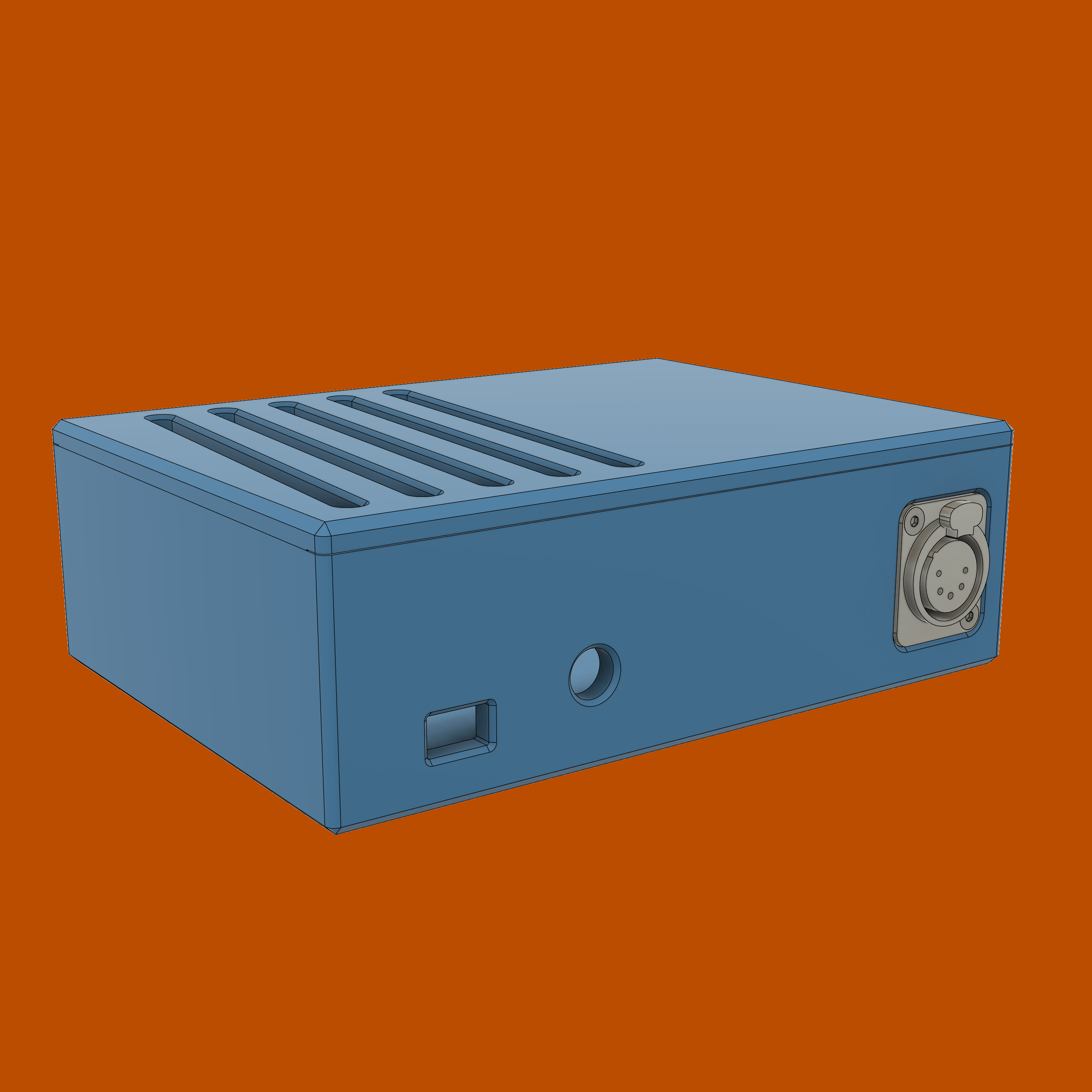
Interactive 3D model preview
Below is not a gif, its a live 3D model renderer which you can rotate via
left click, move around via
right click, and zoom in and out using the mousewheel. Give it a try.
Here will be a live 3d rendederer after i reallocate the assets to stop making cloudflare angry.
High quality audio is much more important than video. Attempting to increase speech intelligebility for remote work meetings and recording video often results in getting a dedicated microphone. A mic needs a stand of sorts. Rigid desk stands can be problematic because all the desk vibrations cause by typing on a keyboard propagate up and cause resonance which gets picked up by a microphone. Spring-equipped stands (usually called boom arms) have two advantages: they “decouple” your mic from the desk so less vibrations travel through, and they make it easier to reposition the mic. Getting one is often an inexpensive way to further
What sets a good boom and and a poor one apart?
Acquire
In June of 2021 I’ve stumbled upon a listing titled “Lot of 2: Yellowtec m!ka Mic Arm M (used)”. They were missing mounting adapters, XLR connectors, and the integrated lighting indicators were of the old style: red color only. Looked like they were decomissioned from a studio somewhere, and had minor surface wear marks, but nothing major. Asking price for both was around half of what a brand new costs, so I figured it wasn’t too bad. Physical inspection confirmed that all internal tension cables and brass bushings were intact, awesome! I went ahead and bought them.
Complete the set
To actually use the boom arms I needed to get what was missing and replace the old and worn out parts:
Mounting hardware
Yellowtec’s m!ka family is a modular system with practically every mounting option imaginable.
Video: How to mount m!ka Microphone Arms (click to reveal)
I’ve decided to order regular table clamps(P/N YT3210), and added plastic sleeves(P/N YT3247) for the boom arms’ ends, since they came in bare.
Light indicaors
Replace the mic arm adapters with the modern dual-color LED(P/N YT3350) ones. The process is demonstrated in Yellowtec’s video and takes about a minute
Video: Yellowtec Tutorial - How to replace your m!ka Mic Adapter (click to reveal)
Terminate the cables
Yellowtec boom arms have internal, non-removable cables. More often than not you’ll find them on sale unterminated, which, I argue, is better compared to ordering a pre-terminated boom arm. Doing more work doesn’t sound right, but the benefit of an unterminated cabling is that you can use the best XLR connector available on the market: the EMC version made by the best maker – Neutrik. Basic XLR connectors by Neutrik are already excellent, but the EMC version is truly the best, here’s a video by Allen – a professional boom operator working in the motion picture industry. I’ve learned a lot from his videos:
Video: How To Solder XLR Microphone Cables [Step-By-Step Tutorial] (click to reveal)
Terminate the cables with one male XLR-5 connector, and one XLR-3 connector.
This was a quick and easy soldering job. There are countless videos on YouTube, as well as XLR-specific soldering tutorials, but I’d like to mention one more resource that I found invaluable while learning to solder: NASA’s Workmanship Standard For Crimping, Interconnecting Cables, Harnesses, And Wiring (page 102 might be helpful).
The EMC-XLR Series is a specifically designed version of the XX series to give enhanced RF screening for critical applications in live performance and recording where there are particular problems with radio transmission or mobile phones. The design guarantees a continuous RF shield connection from the cable to the chassis connector housing via a circular capacitor around the cable shield. The circular capacitors act as high-pass filter with a cut-off frequency around 10 MHz.
An EMI suppression ferrite bead with 24 Ohm at 1 MHz between pin 1 and the cable screen provides a low-pass filter for improved RF rejection.
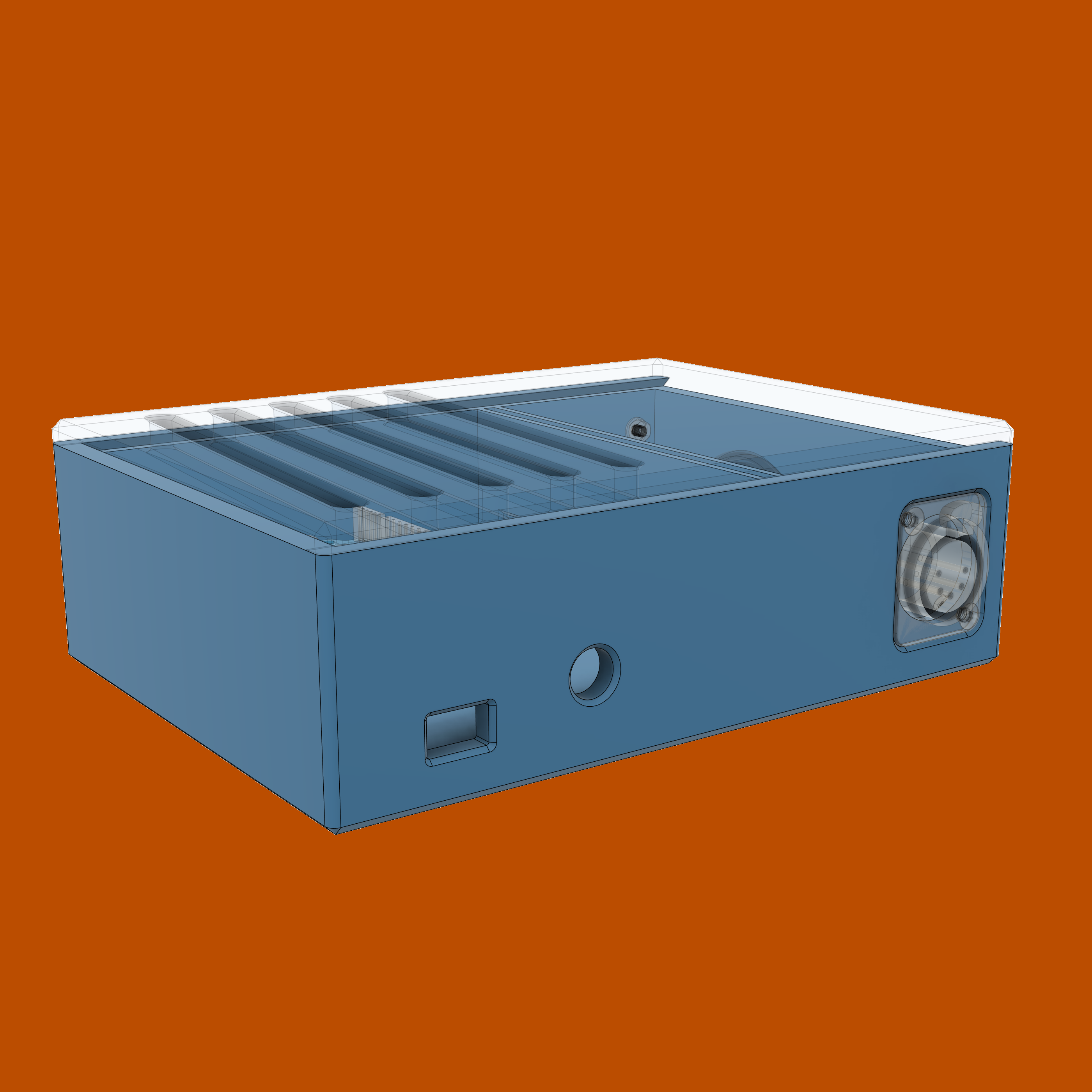
Using fillet instead of chamfer in Autodesk Fusion to process the outer corners results would have resulted in reduced printing time and “prettier”-looking box. made printing faster, but mixing visual features. Issue visualized But as everything in Fusion, the order of operations matter, so using fillet first, and then chamfer fixes the issue. Fixed version.
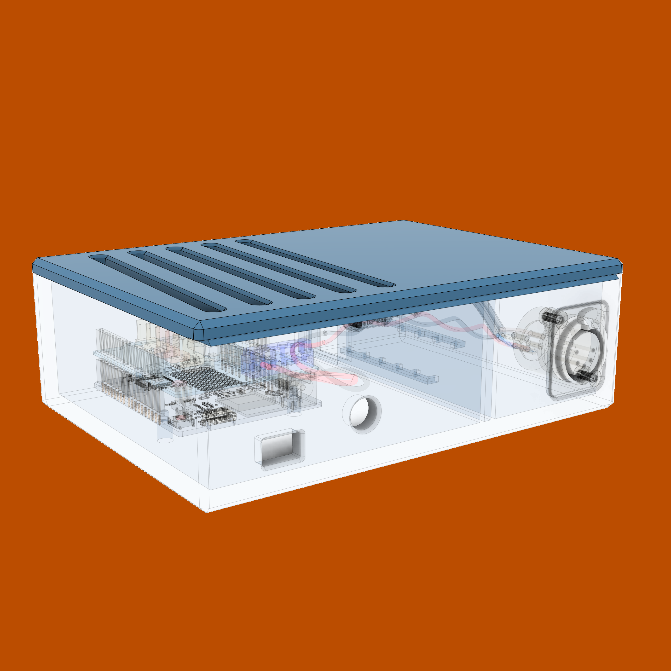
I opted to mount arduino on through-hole pins instead of using brass inserts and screws combo, or through-plastic threads. Screwing things down is more secure, but I’ve learned that brass inserts aren’t ubiquitous, and some 3D printers’ lack of “resolution” and precision characteristics don’t allow printing threading connections of a small diameter. Self-tapping, flexible connection points, and other techniques often used in 3D printing are available. I might improve that part of the design in the future if I feel like it. Current design is good enough for a static box.
The lid does not firmy click in place. Again, the dovetail is good enough for a static box, but may be improved.